
IDMT Curve Calculator
Operate time of inverse-time overcurrent relays: t = k × [ A / ((I/I>)C − 1) + B ]
1. Settings
2. Result
3. Find k for a target time
4. Curve chart (log-log)
5. Test points for secondary injection
| I/I> | Inject I (A) | t theory (s) | t min (s) | t max (s) |
|---|
The IDMT formula behind every curve
All 13 curves use one equation. Only three constants change from curve to curve.
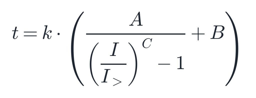
- t: operate time in seconds.
- I: the current the relay measures.
- I>: the start (pickup) setting. Same unit as I, primary or secondary, as long as both match.
- k: the time multiplier. IEC relays call it TMS. ANSI relays call it time dial (TD).
- A, B, C: the curve constants. A sets the overall time level. B adds a fixed time. C sets how steep the curve is.
The ratio I/I> is the key number. Engineers call it the multiple of pickup, or M. At M = 1 the denominator is zero and the time goes to infinity. That is why the relay never trips at exactly its pickup.
IEC 60255-151 writes the same law with k and α in place of A and C, and no B term. IEEE C37.112 writes A, B and p. The physics is the same. Only the letters change.
Curve constants for all 13 curves
These are the constants the calculator uses. They match the curve tables in common numerical relay manuals. The last two columns show the operate time at k = 1, so you can compare curve shapes at a glance.
| Curve | A | B | C | t at 2 × I> (s) | t at 10 × I> (s) |
|---|---|---|---|---|---|
| IEC Normal Inverse | 0.14 | 0 | 0.02 | 10.03 | 2.97 |
| IEC Inverse | 0.14 | 0 | 0.02 | 10.03 | 2.97 |
| IEC Very Inverse | 13.5 | 0 | 1.0 | 13.50 | 1.50 |
| IEC Extremely Inverse | 80.0 | 0 | 2.0 | 26.67 | 0.81 |
| IEC Short Time Inverse | 0.05 | 0 | 0.04 | 1.78 | 0.52 |
| IEC Long Time Inverse | 120 | 0 | 1.0 | 120.0 | 13.33 |
| ANSI Moderately Inverse | 0.0515 | 0.1140 | 0.02 | 3.80 | 1.21 |
| ANSI Normal Inverse | 0.0086 | 0.0185 | 0.02 | 0.64 | 0.20 |
| ANSI Very Inverse | 19.61 | 0.491 | 2.0 | 7.03 | 0.69 |
| ANSI Extremely Inverse | 28.2 | 0.1217 | 2.0 | 9.52 | 0.41 |
| Long Time Inverse | 0.086 | 0.185 | 0.02 | 6.35 | 2.01 |
| Long Time Very Inverse | 28.55 | 0.712 | 2.0 | 10.23 | 1.00 |
| Long Time Extremely Inverse | 64.07 | 0.250 | 2.0 | 21.61 | 0.90 |
IEC Normal Inverse and IEC Inverse share the same constants. Some relays list both names for menu compatibility. Results are the same.
The six core curves (IEC Normal, Very and Extremely Inverse, plus IEEE Moderately, Very and Extremely Inverse) are the ones defined in IEC 60255-151 and IEEE C37.112. The short-time and long-time variants are vendor curves. Check your relay manual before you trust them on a specific device.
How to use the calculator
- Pick the curve. The A, B and C fields fill in by themselves. Choose Custom if your relay uses other constants.
- Enter the start value I>. Use primary or secondary amps. Just keep the fault current in the same unit.
- Enter the time multiplier k. TMS on an IEC relay, time dial on an ANSI relay.
- Enter the fault current I. The result box shows the operate time, the multiple of pickup and the time in cycles.
- Read the formula line. It shows every value plugged in, so you can check the math by hand.
- Use “Find k” if you work the other way. Type the trip time you need. The tool gives the k that gets you there.
- Build your test sheet. Type the multiples you want to inject. The table gives the current, the theoretical time and the pass window.
Worked example
A feeder relay is set to IEC Normal Inverse, I> = 100 A, k = 0.1. A fault of 500 A flows.
- Multiple of pickup: M = 500 / 100 = 5.
- 5^0.02 = 1.0327, so the bracket is 0.14 / 0.0327 = 4.28.
- Operate time: t = 0.1 × 4.28 = 0.428 s.
Now say coordination needs 0.5 s at the same 500 A. Divide 0.5 by 4.28 and you get k = 0.117. Most relays step k in 0.01, so set 0.12. That gives 0.514 s. Recheck it against the downstream device before you lock it in.
Which curve fits which job
The steeper the curve, the more the trip time drops as fault current rises. Steepness comes from C. A C of 0.02 gives a flat curve. A C of 2 gives a steep one.
| Curve family | Shape | Typical use |
|---|---|---|
| IEC Normal Inverse, ANSI Moderately Inverse | Flat (C = 0.02) | Networks where fault current changes a lot with source strength. Time stays fairly stable. |
| IEC Very Inverse, ANSI Very Inverse | Medium (C = 1 or 2) | Feeders where fault current falls off clearly with distance. |
| IEC Extremely Inverse, ANSI Extremely Inverse | Steep (C = 2) | Grading with fuses and riding through motor starting or transformer inrush. |
| IEC Short Time Inverse | Flat and fast | Fast clearing where grading margins are small. |
| IEC Long Time Inverse and Long Time curves | Slow | Overload and earth-fault backup, where you want seconds, not cycles. |
Two practical points:
- Match the family to the network. Mixing IEC and ANSI curves on the same radial feeder works, but grading gets harder. The curves cross at some current. Draw both on one chart before you trust the margin.
- Turn on “Show all curves” in the calculator. It plots every curve at your k on the same chart. You see at once where they cross and which one clears faster at your fault level.
Testing an IDMT curve on site
A curve check is a timing test at several currents. You inject a known multiple of I>, start the timer with the injection and stop it on the trip contact. Then you compare the time with the theory.
Good test points: 2, 3, 5, 7, 10 and 20 times I>. They spread evenly on a log scale. Most relay manuals state curve accuracy between 2 and 20 times pickup, so these points sit inside the guaranteed range.
Pass window: take the relay’s stated accuracy. A common figure is ±5 % of the theoretical time or ±20 ms, whichever is larger. The calculator builds this window for you. Change both values to match your relay’s accuracy class.
Mistakes that fail good relays:
- Wrong unit for I>. The setting is in primary amps but you inject secondary. Divide by the CT ratio first.
- Testing near 1 × I>. At 1.1 or 1.2 × I> the time swings hard with a tiny pickup error. A 2 % pickup offset can shift the time by tens of percent.
- Forgetting the 20 × cap. Above 20 × I> many relays hold the 20 × time. Your measured time looks too slow, but the relay is right.
- Timer on the breaker, not the relay. If you time the breaker auxiliary contact, add the breaker opening time to the theory.
- Wrong curve variant. IEC Normal Inverse and ANSI Normal Inverse are not the same curve. Check the exact name in the relay menu.
- Low test set output at high multiples. At 20 × I> on a 5 A relay you need 100 A. Check your test set can hold that current long enough without heating up or clipping the waveform.
FAQ
What does IDMT mean? Inverse Definite Minimum Time. The trip time gets shorter as the current rises, but it never drops below a minimum set by the curve shape.
What is the formula for the IEC Normal Inverse curve? t = k × 0.14 / ((I/I>)^0.02 − 1). At 10 times pickup and k = 1 it gives 2.97 s.
Is TMS the same as time dial? They do the same job. Both scale the curve up or down. IEC relays use TMS, often 0.05 to 1. ANSI relays use time dial, with a range that depends on the maker.
Why does the calculator show no trip at I/I> = 1? At exactly pickup the formula divides by zero. The theoretical time is infinite. Real relays start slightly above I> and their times near pickup are not guaranteed.
What tolerance should I use when testing? Use the accuracy stated in your relay manual. ±5 % or ±20 ms, whichever is larger, is a common value. It is not a fixed rule.
Can I use this for earth-fault relays? Yes. The same curves apply to 51N and 51G elements. Enter the earth-fault start value as I> and the residual current as I.
Why are IEC Normal Inverse and IEC Inverse identical? Some relays list both names. They share A = 0.14 and C = 0.02, so the times are the same.
Does the calculator work on mobile? Yes. It runs in the browser with no download. You can use it on site from your phone.